
5V 1 Channel Low Level Relay Module with Optocoupler
$0.36
♦ Specifications
Trigger Voltage: 5 VDC
Trigger Current : 20 mA
Maximum Switching Voltage: 250VAC@10A; 30VDC @10A
Single Pole Double Throw (SPDT) Configuration
Power supply indicator lamp
Brand: TongLing/BESTEP/Generic
Combine shipping available. Message us for shipping rates.
- Quality Assurance
- Fast Worldwide Shipping
- Buy with Confidence
Description
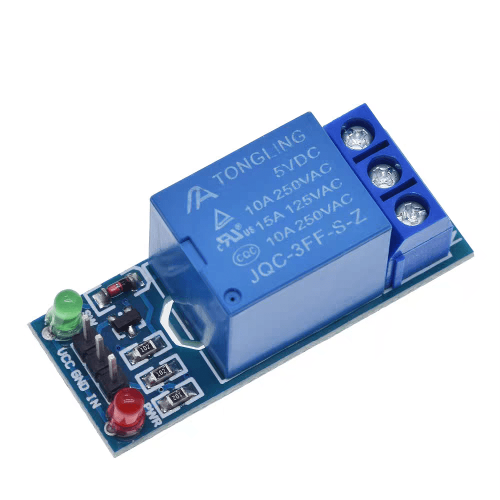
One channel relay module
This module is designed for switching only a single high powered device from your Arduino. It has a relay rated up to 10A per channel at 250VAC or 30VDC. Each relay can switch variety of AC or DC high voltage, high current loads working at 110V or 220V AC mains like lights, fans, and motors and such. The status of relay is indicated by the RED Led.
LED Indication of Relay ON.
Direct input from 3-5V Microcontroller for relay control.
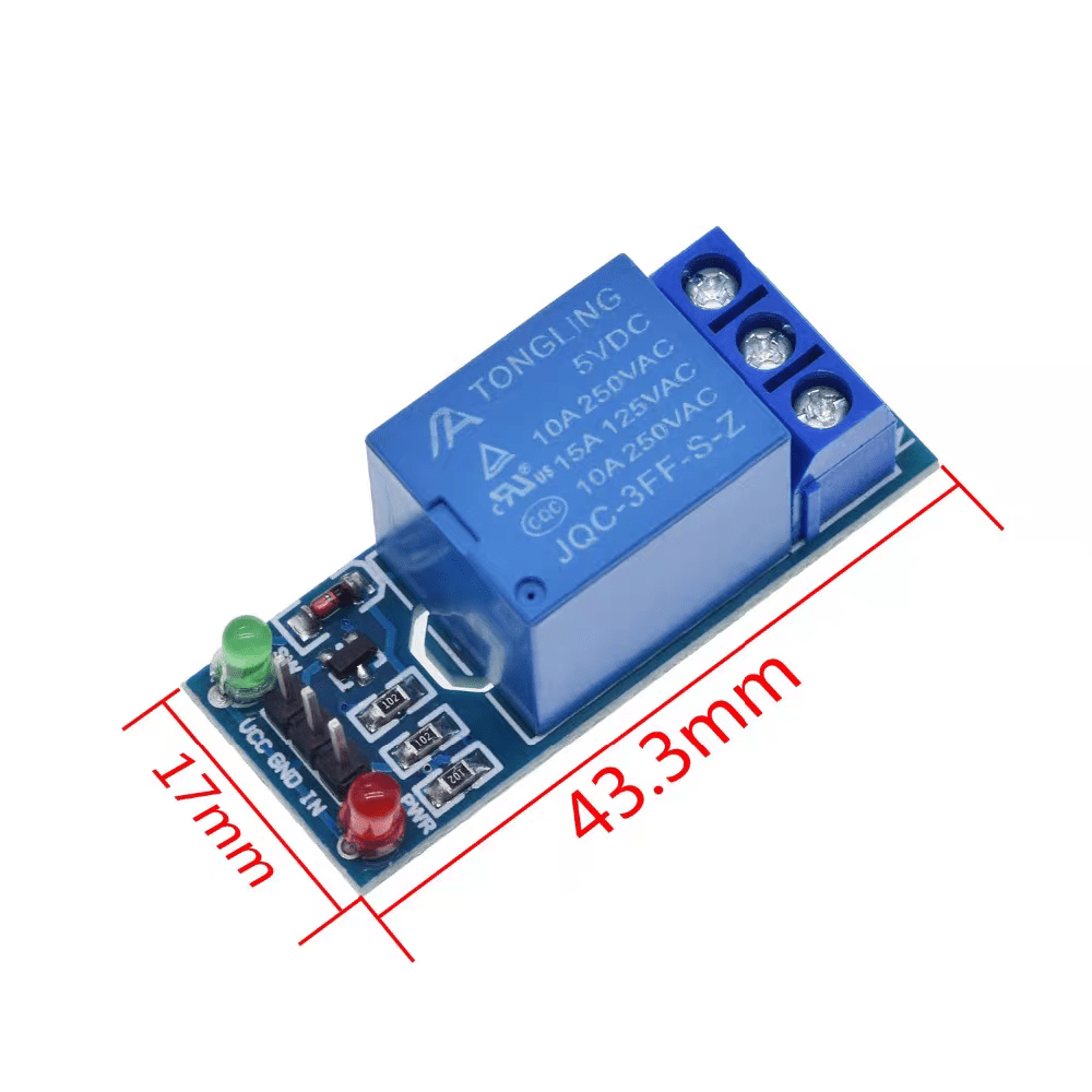
Output terminal for relay contacts.
Provision of 2×3 pin male header for wire connection.
Powered from external 5V or from male header.
Electromagnetic relays are employed for the protection of various ac and dc equipment.
The over/under current and voltage protection of various ac and dc equipment.
For differential protection.
Multiple DIY projects
Getting started with the Single Channel 5V Relay Module
Sometimes you want your Arduino to control AC powered devices like lamps, fans or other household devices. But because the Arduino operates at 5 volts, it cannot directly control these higher voltage devices. That’s where the relay module comes in. You can use a relay module to control the AC mains and Arduino to control the relay.
This tutorial walks you through how to setup the one channel relay module to switch on a lamp or other device, but let’s begin with a short introduction into relays.
How Do Relays Work?
A relay is an electromagnetic switch operated by a relatively small current that can control much larger current. Here’s a simple animation illustrating how the relay uses one circuit to switch on another circuit.
Relay working animation 1.
Initially the first circuit is switched off and no current flows through it until something (either a sensor or switch closing) turns it on. The second circuit is also switched off.
When a small current flows through the first circuit, it activates the electromagnet, which generates a magnetic field all around it.
Relay Basics
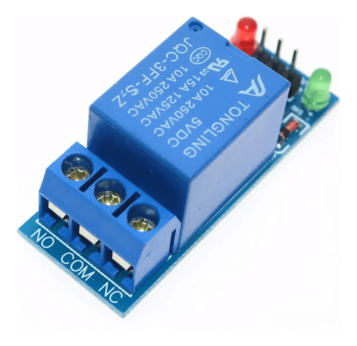
Typically the relay has 5 pins, three of them are high voltage terminals (NC, COM, and NO) that connect to the device you want to control.
Relay pinout
The mains electricity enters the relay at the common (COM) terminal. While use of NC & NO terminals depends upon whether you want to turn the device ON or OFF. Between the remaining two pins (coil1 and coil2), there is a coil that acts like an electromagnet.
Relay working animation 2
When current flows through the coil, the electromagnet becomes charged and moves the internal contacts of the switch. At that time the normally open (NO) terminal connects to the common (COM), and the normally closed (NC) terminal becomes disconnected.
When current stops flowing through the coil, the internal contact returns to its initial state i.e. the normally closed (NC) terminal connects to the common (COM), and the normally open (NO) terminal reopens.
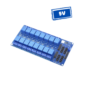
One Channel Relay Module
For this tutorial, we are going to use one channel relay module. However there are other modules with two, four and eight channels. You can choose the one that best suits your needs.
Reviews
There are no reviews yet.